
Air Filters and Air Filtration Solutions - US
We specialize in general commercial and industrial air filtration, welding shop filtration systems, automatic and robotic welding cell filtration, and oil mist and Air Filtration solutions for Commercial and Industrial situations. Whether your challenge are stems from welding fumes and smoke; laser and cutting fumes and smoke; grinding and dust; dry dust; powders; machine processes; mist removal; sanding and finishing; vehicle exhaust or dust collection, we’ve got you covered.
Search By Product, Application or Industry


Need Industrial Air Filters or Cartridges? Choose the appropriate option for quick ordering. Now with Free Shipping!
Featured products
-
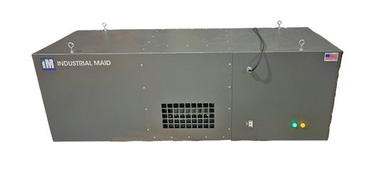
T3000S-MM Air Filtration Unit
SKU: AIR-A007
Regular price $2,499.99Regular priceUnit price per -
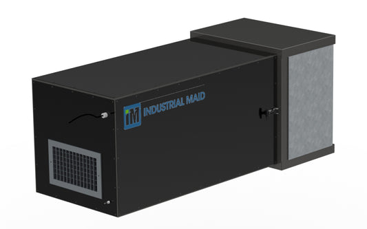
2500 Commercial Air Cleaner 2500 CFM
SKU: 2500-STOCK
Regular price $3,581.00Regular priceUnit price per -
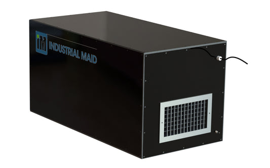
2000C - Commercial Air Cleaner 2000 CFM
SKU: 2000C-STOCK
Regular price $2,580.00Regular priceUnit price per

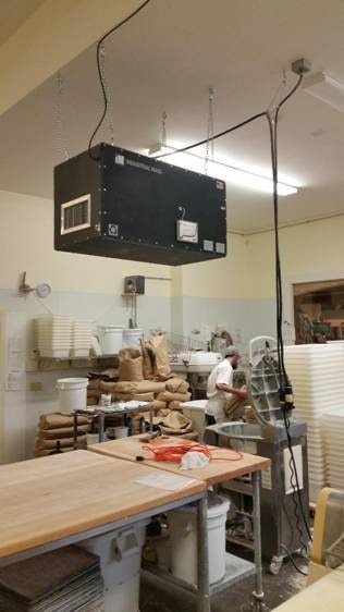
You're in a healthy place with Industrial Maid
Go Ahead, Breathe Easy, knowing you’re working with a company that started 19 years ago because we saw a better, more efficient, cost-effective and environment-friendly way to ensure your shop is clean, your employees are healthy, and your air quality is high. You’re at the best spot to find commercial and industrial air filtration solutions for your business with Industrial Maid.
